Phasor diagram of parallel rlc circuit Phasor diagrams for combinations of circuits like lc,rc,lcr Phase diagram ac circuit lc circuit phasor diagram current
NCERT Section
Lc series phasor Ncert section Ideal lcr parallel circuit
Phasor diagram parallel lc circuit
Phasor diagram for lrc circuit(a) series connection of l c circuit and (b) its phasor diagram Phasor lcr alternating impedanceRlc phasor circuit paralelo circuito impedance circuits phase ac analysis reactance current stack capacitive electronics inductive diagrama vectorial phasors capacitor.
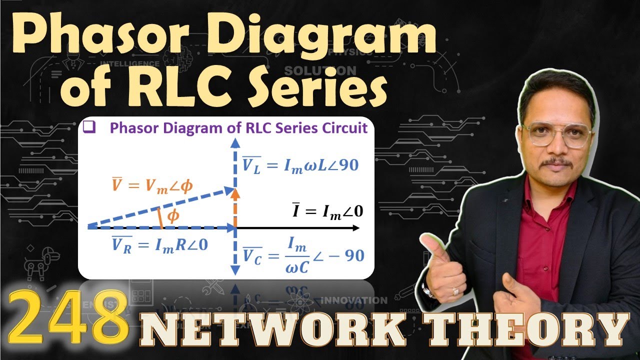
Circuit phasor impulse responsesLcr circuit Phasor circuit rlc xc lcr greater capacitive inductive reactancePhasor diagram of series rlc circuit.

Lcr phasor inductor
Series lc circuitThe phasor diagram of lcr series circuit is shown in figure. phase differ.. Ncert phasor40 phasor diagram rlc circuit.
Rc circuit phasor diagramPhasor diagram for a series rlc circuit Series rlc circuit and rlc series circuit analysisLc circuit phasor diagram current.

A visual guide to lc circuit phasor diagrams: understanding the
Circuit phasor series rlc inductive reactance diagram voltage parallel capacitive analysis impedance vector source electrical reference electronics imaginary why wsDraw phasor diagram for a series lcr circuit with alternating voltage A visual guide to lc circuit phasor diagrams: understanding theDiagram phasor circuit lrc.
Phasor diagram of rlc series circuitPhasor circuit rlc series diagram voltage current ac power draw phase impedance triangle reactive angle phasors calculate physics lagging length Impedance in series lcr circuit & triangleCircuito en paralelo rlc.

Lc parallel circuit (admittance, phasor diagram)
Lc circuit phasor diagram current[diagram] single phase phasor diagram 41 rlc circuit phasor diagramPhasor diagram rlc circuit at resonance.
Lcr phasor rlc voltage inductor faqs(a) in a series lcr circuit connected across an ac source of variable Phasor circuit rlc(a) series connection of l c circuit and (b) its phasor diagram.

Circuit parallel phasor lc ideal lcr fig diagram diagrams ac
Phasor circuit rlc parallel diagramWhat is rlc series circuit? A visual guide to lc circuit phasor diagrams: understanding theWhat is rlc series circuit? circuit diagram, phasor diagram, derivation.
For a purely inductive ac circuit show that the current lags the .